
The Power Probe 3’s instruction manual, available at static1.squarespace.com, details its use for circuit testing. Careful operation prevents ECU damage, as noted in forums like ScannerDanner.
What is a Power Probe 3?
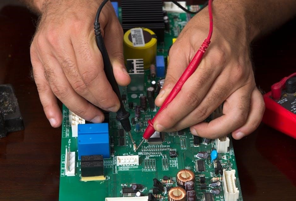
The Power Probe 3 is a versatile electrical testing tool designed for automotive and other low-voltage DC systems. It functions as a power source, a ground, and a diagnostic tester, all in one handheld device; Crucially, understanding its operation requires consulting the official instruction manual, readily accessible online at static1.squarespace.com. This manual details safe and effective usage, emphasizing the potential for circuit overload and subsequent damage to sensitive components like ECUs and PCMs.
Forums, such as ScannerDanner, highlight the importance of caution, stressing that improper grounding can lead to costly repairs. The Power Probe 3 simplifies locating shorts and opens, but responsible use, guided by the manual, is paramount.
Key Features and Benefits
The Power Probe 3 boasts several key features, streamlining electrical diagnostics. It provides power, ground, and testing capabilities in a single tool, reducing the need for multiple instruments. The instruction manual (static1.squarespace.com) details how to utilize these features for efficient circuit integrity testing, locating shorts, and identifying open circuits.
Benefits include faster troubleshooting, reduced diagnostic time, and minimized risk of damaging vehicle electronics – a concern frequently discussed on platforms like ScannerDanner. Proper use, as outlined in the manual, prevents accidental ECU overload. The Power Probe 3 empowers technicians with a comprehensive and effective diagnostic solution.
Safety Precautions
Prioritize safety when using the Power Probe 3. The instruction manual (static1.squarespace.com) emphasizes careful operation to avoid damaging sensitive electronic control units (ECUs) or modules. Forums like ScannerDanner highlight the risk of circuit overload and potential ECU burnout if grounding is improperly applied.
Always verify proper grounding before applying power. Understand amperage limits to prevent component failure. Never assume a circuit is safe without testing. Review the manual thoroughly before each use, paying close attention to warnings regarding voltage and current. Following these precautions ensures safe and effective diagnostics.

Understanding the Power Probe 3 Components
The Power Probe 3, as detailed in its manual (static1.squarespace.com), features a probe tip, power button, grounding clip, and LED indicators for diagnostics.
Probe Tip and Interchangeable Options
The Power Probe 3’s probe tip is central to its functionality, enabling direct contact with circuits for power and ground testing. The instruction manual (static1.squarespace.com) highlights the availability of interchangeable tip options, crucial for accessing various connection points within a vehicle’s electrical system. These options allow technicians to navigate tight spaces and make secure contact with different terminal types.
Selecting the correct tip ensures accurate readings and prevents damage to both the probe and the vehicle’s wiring. The manual emphasizes the importance of inspecting tips for wear and tear, replacing them as needed to maintain optimal performance. Different tips cater to specific testing scenarios, enhancing the probe’s versatility and diagnostic capabilities. Proper tip selection is a key aspect of effective circuit testing.
Power Button and Activation
The Power Probe 3’s activation relies on a straightforward power button, detailed within the instruction manual available at static1.squarespace.com. Upon pressing the button, the probe initiates its testing functions, delivering power or ground through the selected tip. The manual stresses the importance of understanding the activation sequence to avoid unintended circuit energization or grounding.
A firm, deliberate press ensures reliable activation, while accidental contact should be avoided. The probe’s responsiveness is crucial for accurate diagnostics. The manual also covers scenarios where the power button may not function correctly, offering troubleshooting steps. Proper activation is fundamental to safe and effective use, preventing potential damage to sensitive electronic components within a vehicle.
Grounding Clip and Connection
The Power Probe 3’s grounding clip, as explained in the manual found at static1.squarespace.com, is vital for completing circuit tests. It establishes a return path for current, enabling power or signal flow. The manual emphasizes secure connection to a clean, unpainted metal surface for optimal conductivity. Poor grounding leads to inaccurate readings and potential damage.

Users must avoid grounding to components directly connected to the ECU/PCM, as highlighted on ScannerDanner forums, to prevent module burnout. The manual details proper grounding techniques, including clip placement and inspection for corrosion. A solid ground connection is paramount for safe and reliable operation, ensuring accurate diagnostics and minimizing the risk of electrical system issues.
LED Indicators and Their Meanings
The Power Probe 3 utilizes LED indicators to communicate its operational status, as comprehensively detailed in the official instruction manual available on static1.squarespace.com. These indicators signal power availability, ground connection quality, and overload conditions. A solid power LED confirms proper voltage, while a flashing LED may indicate a low battery or internal fault.
The manual stresses the importance of understanding these signals to avoid misdiagnosis and potential damage, a concern frequently discussed on forums like ScannerDanner. Overload protection activation is also indicated by a specific LED, prompting immediate cessation of testing. Correct interpretation of these LEDs ensures safe and effective use of the tool.

Basic Operation of the Power Probe 3
The Power Probe 3, guided by its manual (static1.squarespace.com), tests power, ground, and circuit integrity. ScannerDanner users caution against overloading circuits during testing.
Power Testing Procedure
To perform a power test with the Power Probe 3, consult the official instruction manual located at static1.squarespace.com for detailed steps and safety guidelines. Begin by connecting the grounding clip to a known good ground. Then, carefully touch the probe tip to the circuit you wish to test for power.
The LED indicators will illuminate, signifying the presence or absence of voltage. Remember, as highlighted in ScannerDanner forums, improper grounding or excessive probing can damage sensitive electronic components like ECUs. Always verify the circuit’s expected voltage before applying the probe. Prioritize caution and refer to the manual for specific voltage ranges and troubleshooting tips. A systematic approach, guided by the manual, ensures accurate results and prevents potential damage.
Ground Testing Procedure
For ground testing using the Power Probe 3, the instruction manual (static1.squarespace.com) is crucial. Securely attach the grounding clip to a confirmed good ground point on the vehicle. Activate the Power Probe 3 and touch the probe tip to the circuit’s ground path.
A properly functioning ground will illuminate the appropriate LED indicator. ScannerDanner forum discussions emphasize the risk of applying unintended grounds, potentially damaging the ECU or other modules. Therefore, meticulous verification is essential. Always double-check the grounding point before testing. The manual details proper grounding techniques and cautions against creating false grounds. Following these guidelines minimizes the risk of electrical damage and ensures accurate diagnostic results.
Circuit Integrity Testing
Circuit integrity testing with the Power Probe 3, as detailed in the instruction manual (static1.squarespace.com), verifies continuous electrical paths. Activate the probe and touch the tip to one end of the circuit, then connect the grounding clip to the other. A lit LED confirms continuity.
ScannerDanner forum users caution against unintended grounding during this process, highlighting the potential for ECU damage. The manual stresses careful application to avoid creating false paths. This test identifies breaks or high-resistance connections. Proper technique, guided by the manual, ensures accurate diagnosis. Remember to disconnect power before testing circuits with sensitive components, safeguarding against accidental shorts or damage.
Locating Shorts to Power
Locating shorts to power, as outlined in the Power Probe 3’s instruction manual (static1.squarespace.com), involves carefully probing potential short circuits. Activate the probe and touch the tip to suspected short locations while the circuit is powered. The manual emphasizes caution, as improper use can damage ECUs, a concern echoed on ScannerDanner forums.
A lit LED indicates a direct connection to power, pinpointing the short. Systematically trace the circuit, isolating the fault. Avoid grounding the probe during this process to prevent false positives and potential component damage. The manual details safe practices, stressing the importance of understanding amperage limits to prevent overload and protect sensitive electronics.

Advanced Techniques with the Power Probe 3
Advanced techniques, detailed in the Power Probe 3 manual (static1.squarespace.com), expand testing capabilities beyond basic power and ground checks for complex diagnostics.
Locating Opens in Circuits
Identifying open circuits with a Power Probe 3 requires a systematic approach, as outlined in the official instruction manual available on static1.squarespace.com. The manual emphasizes utilizing the probe’s power application feature to simulate a completed circuit. Begin by disconnecting the suspected open circuit’s power source. Then, inject power directly into the circuit using the probe, working your way along the wiring harness.
A lack of voltage at a specific point indicates the open’s location is upstream. Remember, the ScannerDanner forum highlights the importance of caution; improper grounding can damage sensitive components like ECUs. The manual details safe grounding practices. Regularly check the probe tip for damage, ensuring a solid connection for accurate readings during this process. This methodical approach, guided by the manual, efficiently pinpoints breaks in the circuit.
Testing Relays and Switches
The Power Probe 3, as detailed in the instruction manual found at static1.squarespace.com, simplifies relay and switch testing. To test a relay, apply power and ground through the probe to the coil side, verifying activation. Then, check continuity through the switched contacts. For switches, the manual recommends applying power through the probe to one terminal and grounding the other, observing if the circuit completes when the switch is engaged.
ScannerDanner forum discussions stress caution; avoid overloading circuits. The manual emphasizes proper grounding techniques to prevent ECU damage. Ensure the probe tip is secure for accurate readings. This method bypasses the need for a separate power source and multimeter, streamlining diagnostics. Always refer to the vehicle’s wiring diagram alongside the Power Probe 3 manual for correct terminal identification.
Testing Diodes
The Power Probe 3, guided by the instruction manual available on static1.squarespace.com, can assist in diode testing, though it’s not a dedicated diode tester. Apply power through the probe to the anode (positive side) of the diode and ground the cathode (negative side). A good diode will allow current flow in this direction. Reverse the connections – ground the anode and power the cathode – and the circuit should not complete.
ScannerDanner forum users caution against relying solely on the Power Probe for precise diode readings. It’s best used for a quick functional check. Referencing the vehicle’s wiring diagrams alongside the manual is crucial. Remember proper grounding techniques to avoid damaging sensitive electronic components, as highlighted in online discussions.
Testing Fuses
The Power Probe 3, as detailed in the instruction manual found at static1.squarespace.com, simplifies fuse testing. Power the fuse’s test point with the probe and ground the opposite side. A good fuse will complete the circuit, indicated by the probe’s light or tone. No continuity suggests a blown fuse. However, always visually inspect the fuse for a broken filament – the probe confirms power to the fuse, not internal integrity.
ScannerDanner forum discussions emphasize caution; a seemingly good fuse can sometimes be deceptive. Always use a multimeter for definitive confirmation. Incorrect grounding, a common mistake, can lead to false readings or even ECU damage, so adhere strictly to the manual’s guidance.
Troubleshooting Common Issues
The Power Probe 3 manual (static1.squarespace.com) addresses issues like no power or inaccurate readings. Overload protection and damaged tips are also covered.
Power Probe 3 Not Powering On
If your Power Probe 3 fails to power on, consult the official instruction manual available at static1.squarespace.com for detailed troubleshooting steps. Begin by verifying the probe’s power source and ensuring a secure connection. Check the internal fuse, if accessible, as a blown fuse is a common cause of power failure.
ScannerDanner forum discussions highlight the importance of careful use to avoid circuit overloads, which can potentially damage the probe itself. Ensure the grounding clip is properly connected and that you are not attempting to test circuits beyond the probe’s amperage limits. If the issue persists after these checks, further diagnostics may be required, potentially indicating an internal component failure necessitating professional repair or replacement.
Inaccurate Readings
Experiencing inaccurate readings with your Power Probe 3? The comprehensive instruction manual, found at static1.squarespace.com, provides guidance on calibration and proper usage techniques. Ensure the probe tip is clean and making firm contact with the circuit being tested. Poor connections can significantly affect reading accuracy.
ScannerDanner forum users emphasize the risk of overloading circuits, which can also lead to false readings or damage to the probe or vehicle electronics. Verify the selected voltage range is appropriate for the circuit under test. If inaccuracies persist, check the grounding clip for a secure connection, as a poor ground can introduce errors. Consider battery condition as a potential factor influencing readings.
Damaged Probe Tip
A damaged probe tip compromises the Power Probe 3’s accuracy and safety. The official instruction manual (static1.squarespace.com) details proper handling and replacement procedures. Avoid excessive force when probing circuits, as this can bend or break the tip.
ScannerDanner forum discussions highlight the importance of using the correct tip for the application; incorrect tips can cause damage to both the probe and the vehicle’s wiring. Regularly inspect the tip for wear and tear, and replace it immediately if any damage is detected. A worn or damaged tip can lead to inaccurate readings and potentially short circuits.
Overload Protection Activation
The Power Probe 3 features overload protection to prevent damage to itself and the vehicle’s electrical system. The instruction manual (static1.squarespace.com) explains that activation indicates excessive current draw. ScannerDanner forum users caution against applying grounds carelessly, as this is a common cause of overload.
If overload protection activates, immediately disconnect the probe and investigate the circuit. Check for shorts to ground or excessive resistance. Resetting the probe may require a cool-down period. Repeated activations suggest a deeper issue within the circuit that needs professional diagnosis. Ignoring overload warnings can lead to ECU or module failure.

Comparing Power Probe 3 to Other Tools (ECT3000)
The ECT3000, like the Power Probe 3, locates shorts and opens; however, the ECT3000 offers additional functionality for complex electrical diagnostics.
Power Probe 3 vs. ECT3000: Functionality
Both the Power Probe 3 and the ECT3000 are invaluable tools for automotive electrical diagnostics, but they differ in their capabilities. The ECT3000, as highlighted in various resources, excels at quickly pinpointing wiring shorts and opens within a circuit – a core function shared with the Power Probe 3. However, the ECT3000 expands upon this with more advanced features.
Specifically, the ECT3000 offers a broader range of testing modes and diagnostic options, allowing technicians to delve deeper into complex electrical issues. While the Power Probe 3 focuses on power and ground testing, the ECT3000 provides a more comprehensive suite of tools for circuit analysis. Accessing the Power Probe 3’s instruction manual (static1.squarespace.com) is crucial for understanding its specific functionalities and limitations when compared to the ECT3000’s expanded toolkit.
Power Probe 3 vs. ECT3000: Safety Considerations
Both the Power Probe 3 and ECT3000 demand careful handling to prevent damage to sensitive automotive electronics, particularly the ECU/PCM. Forum discussions on ScannerDanner emphasize the ease with which circuits can be overloaded, potentially “frying” engine control modules. The Power Probe 3 instruction manual (static1.squarespace.com) stresses the importance of proper grounding techniques and understanding amperage limits.
While both tools pose similar risks if misused, the ECT3000’s expanded functionality might introduce additional safety considerations due to its more complex operation. Users must diligently follow the guidelines outlined in each tool’s respective manual to avoid unintended consequences. Prioritizing circuit overload prevention and adhering to recommended procedures are paramount when utilizing either diagnostic device.
When to Use Each Tool
The Power Probe 3, as detailed in its instruction manual (static1.squarespace.com), excels at basic power and ground testing, and quickly verifying circuit integrity – ideal for initial diagnostics. It’s a go-to for confirming power delivery and locating simple shorts. The ECT3000, however, shines when pinpointing complex wiring issues like opens and shorts across extensive circuits.
If you need rapid power application for component testing, the Power Probe 3 is efficient. For in-depth troubleshooting requiring locating precise short-to-power locations or open circuits, the ECT3000’s advanced features are invaluable. Consider the complexity of the electrical problem when selecting the appropriate tool for the job.
Resources and Manuals
Power Probe 3 manuals are accessible online at static1.squarespace.com, offering detailed instructions. ScannerDanner forums also provide user support and discussions.
Accessing the Power Probe 3 Instruction Manual (static1.squarespace.com)
The official Power Probe 3 instruction manual is readily available as a downloadable PDF file hosted on static1.squarespace.com. This comprehensive guide provides detailed explanations of the tool’s functionality, covering everything from basic operation to advanced diagnostic techniques. Users can find crucial information regarding safety precautions, component identification, and troubleshooting procedures within this document.
Specifically, the manual outlines proper testing methodologies for power, ground, and circuit integrity, emphasizing the importance of avoiding potential damage to sensitive vehicle electronics like the ECU or PCM. It’s a vital resource for both novice and experienced technicians, ensuring safe and effective utilization of the Power Probe 3. Accessing and reviewing this manual before operation is highly recommended, as highlighted by discussions on platforms like ScannerDanner.
Power Probe IV Manual Reference
While focusing on the Power Probe 3, understanding the Power Probe IV’s manual (available at static1.squarespace.com) offers valuable context. Though a newer iteration, the core principles of circuit testing remain consistent. The IV manual details enhanced features and safety protocols, building upon the foundation established by the PP3.
Both manuals emphasize careful operation to prevent damage to vehicle ECUs and PCMs, a concern frequently discussed on forums like ScannerDanner. Reviewing the PP4 documentation can provide insights into best practices and potential upgrades. It’s crucial to remember that even with advancements, responsible use and adherence to safety guidelines, as outlined in both manuals, are paramount for effective and safe electrical diagnostics.
Online Forums and Support Communities (ScannerDanner)
ScannerDanner forums represent a valuable resource for Power Probe 3 users. Discussions frequently revolve around practical application of the tool and interpreting results, often referencing the official instruction manual found at static1.squarespace.com. Users share experiences, troubleshooting tips, and cautionary tales – like avoiding circuit overloads that can damage ECUs.
These communities provide a platform to ask questions, learn from peers, and gain insights beyond the manual’s scope. Experienced technicians often offer advice on advanced techniques and potential pitfalls. Engaging with ScannerDanner can significantly enhance your understanding and safe operation of the Power Probe 3, supplementing the information within the official documentation.

Potential Risks and Mitigation
The Power Probe 3, per the instruction manual, requires careful use to avoid ECU damage from circuit overload; proper grounding is crucial for safety.
Avoiding ECU/PCM Damage
Protecting the Engine Control Unit (ECU) or Powertrain Control Module (PCM) is paramount when utilizing the Power Probe 3. The instruction manual emphasizes cautious application, as easily overloading a circuit can cause irreversible damage. ScannerDanner forum discussions highlight this risk, warning users about inadvertently applying a ground during testing.
Avoid directly grounding circuits without verifying their intended function first. Incorrect grounding can introduce unintended paths for current, potentially frying sensitive electronic components within the ECU/PCM. Always double-check connections and utilize the Power Probe 3’s features responsibly. Understanding circuit diagrams and proper testing procedures, as detailed in the manual, is essential for preventing costly repairs.
Circuit Overload Prevention
The Power Probe 3, while powerful, demands respect for circuit limitations; The instruction manual stresses the importance of understanding amperage limits to prevent overloads. ScannerDanner forum posts repeatedly caution against applying excessive current, which can damage wiring and electronic modules.
Before initiating any test, verify the circuit’s rated amperage. Avoid prolonged activation of the Power Probe 3 on sensitive circuits. Utilize the tool’s features judiciously, and never attempt to force a connection. Proper grounding techniques, as outlined in the manual, are crucial for establishing a safe testing environment. Always disconnect the Power Probe 3 when not actively in use to minimize risk.
Proper Grounding Techniques
The Power Probe 3’s instruction manual emphasizes secure grounding as paramount for safe and accurate testing. Improper grounding can lead to inaccurate readings and, critically, damage to vehicle ECUs or modules – a concern frequently voiced on forums like ScannerDanner.
Always connect the grounding clip to a clean, unpainted metal surface. Ensure a firm connection to establish a reliable ground path. Avoid grounding to components that may have resistance or be part of the circuit under test. The manual details appropriate grounding points for various vehicle systems. Prioritize safety by verifying the ground connection before activating the probe, minimizing the risk of unintended consequences.

Understanding Amperage Limits
The Power Probe 3’s instruction manual stresses awareness of its amperage limits to prevent circuit overload and potential ECU damage – a risk highlighted in discussions on ScannerDanner. Exceeding these limits can “burn out” sensitive electronic components.
The probe is designed for low-amperage testing, primarily for signal verification and power/ground checks. Avoid using it to power high-current devices or attempt to jump-start circuits. The manual specifies the maximum amperage the probe can safely handle. Always consult the vehicle’s wiring diagrams to understand the current draw of the circuit being tested. Prioritize caution and adhere to the specified limits for reliable and safe operation.